
- #SOLIDWORKS FLOW SIMULATION ANGLE OF ATTACK FULL#
- #SOLIDWORKS FLOW SIMULATION ANGLE OF ATTACK SOFTWARE#
- #SOLIDWORKS FLOW SIMULATION ANGLE OF ATTACK CODE#
- #SOLIDWORKS FLOW SIMULATION ANGLE OF ATTACK SERIES#
Second digit describing the distance of maximum camber from the airfoil leading edge in tenths of the chord. The pressure gradient between these two surfaces contributes to the lift force generated for a given airfoil. The NACA four-digit wing sections define the profile by.
#SOLIDWORKS FLOW SIMULATION ANGLE OF ATTACK CODE#
The parameters in the numerical code can be entered into equations to precisely generate the cross-section of the airfoil and calculate its properties. The various terms related to airfoils are defined below. Look at curvature combs to check for nasty distortions.When oriented at a suitable angle, the airfoil deflects the oncoming air for fixed-wing aircraft, a downward forceresulting in a force on the airfoil in the direction opposite to the deflection. Add some extra guide curves to keep this under control. 2D Airfoil: Multiparametric Optimization in Flow Simulationīeware of lofts as they can distort the shape. I expect that it will then need to be exploded for a proper sweep. You can then make a sketch block and paste it onto any plane.

The trailing edge should have a thickness that relates to the boundary layer thickness and construction limitations.Ī minimum of 0. Redo the constraints at leading edge circle and trailinge edge line.

Remove constraints and convert to proportional curves. Adjust the upper and lower surface splines watching cruvature combs. Activate curvature combs and you will see the irregular rate of change of curvature.Ĭreate a new airfoil shape with a circular leading edge, and a squared off trailing edge, draw a new spline with only a few control points snapped to the original data. The spline that solidworks creates has some poor aerodynamic qualities. His interests include engineering, simulation, team leadership, and predictive analytics.Insert curve will get the data points into solidworks. Flow Simulation solver Initial output I get is an Excel sheet with my three input parameters and my three selected goals: lift coefficient, drag coefficient, and lift-drag ration.
#SOLIDWORKS FLOW SIMULATION ANGLE OF ATTACK FULL#
In my next blog, I will explore a full 3D wing and reveal more of the power of Multiparameter Optimization in Flow Menu Toggle navigation. Of course there were more variables at play for the Wright Flyer than just airfoil, including the 3D wing shape planform area and aspect ratio and dihedral angle. The resulting airfoil looks similar to the wing shape of the Wright Flyer - the first to achieve controlled, powered, manned flight. The output function can be defined as a linear weighted combination of any of your defined goals. I might want an airfoil with higher lift coefficient, even though it might not be the simple highest lift-drag ratio. This makes sense, and resembles a section used on a glider. The airfoil geometry with the absolute highest lift-drag ratio is skinny, low-cambered, and max camber location near the leading edge. So, in just a few hours I was able to create this response plot to understand how lift and drag varied against thickness, camber, and position of max camber. Initial output I get is an Excel sheet with my three input parameters and my three selected goals: lift coefficient, drag coefficient, and lift-drag ration. Kb4019990īefore beginning this design study, I made sure to optimize my mesh and calculation controls to get an accurate enough answer in a minimum amount of time. We then specify how many Experiments to create.

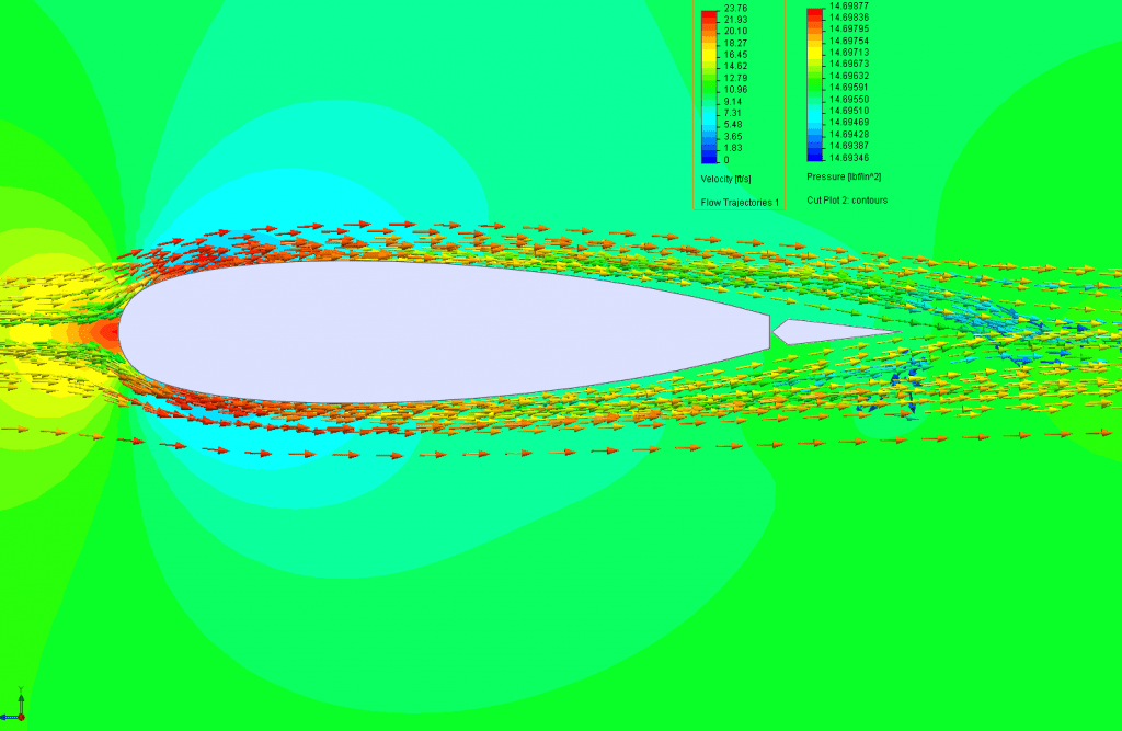
Some quick tips are to use equidistant mesh control and at least one Solution Adaptive mesh refinement to capture the complex pressure field that develops. My study is a 2D domain and is a fixed 6 degree angle of attack. I used this because I had previously validated my meshing strategy by matching to NACA section lift and drag results with these same flow conditions. I set up the base sketch to vary in airfoil thickness, camber, and position of max camber. This means we can set up a Design of Experiments in Flow, varying model or study characteristics and evaluating the performance of our design.
#SOLIDWORKS FLOW SIMULATION ANGLE OF ATTACK SOFTWARE#
Today, we engineers have access to incredible software and computing power. Specifically, they investigated 2D airfoil characteristics of camber curvature and thickness, as well as 3D wing parameters like planform aspect ratio and shape.
#SOLIDWORKS FLOW SIMULATION ANGLE OF ATTACK SERIES#
They crafted a series of parametric experiments to explore the relationship between wing shape and aerodynamic performance. In the Fall and Winter ofOrville and Wilbur Wright completed the most comprehensive study of airfoils to-date in their experimental wind tunnel in Dayton, Ohio.


 0 kommentar(er)
